 |
PandA-2024.02
|
|
PandA-2024.02
|
The storage value insertion phase inserts additional nodes in the scheduled data flow graph. Each edge that crosses a cycle step boundary represents a value that has to be stored somewhere. The storage allocation function can therefore be defined as the following transformation:
Given a scheduled data flow graph  , the storage value insertion is a transformation
  , which adds storage value
  to the graph such that all edges
  which cross a cycle step boundary are connected to a storage value.
The register allocation problem can be formulated as the allocation of a storage module  for each storage value :
Register allocation: the register allocation function  , identifies the storage module holding a value from the set
The binding information is needed for evaluating and/or performing the register optimization. Therefore, the accurate estimation of the number of registers requires both scheduling and binding.
The main task to provide good solutions to the register allocation problem is the procedure used to recognize the overlapping of the life time intervals. Since a register is needed for the values alive between two control steps, the analysis can be easily performed on state transition graph (see Finite State Machine). In fact, a vertex in this graph represent all operations executed in a control step. The value that will be further needed will be alive across the edges outcoming from this vertex. Besides, an edge represents the changing from a control step to the next one, so the values alive between two control steps are the values alive on this edge. The dataflow analysis, presented by Appel, allows to compute, for each edge, which are the variables alive. These variables will be the vertices of a conflict graph, that is a graph so defined:
The resulting conflict graph is minimal with respect to number of conflicting variables (i.e. the number of edges in the graph). In a such way, the solution to register allocation problem will use the minimum number of registers. The problem can be formulated as a clique-covering problem (search of largest cliques into the compatibility graph, complementary to the conflict one) and it can be easily resolved with an heuristic vertex coloring on conflict graph. An heuristic coloring assigns a different color to source and target of each edge. So variables alive in the same moment will be connected all together by conflict edges, so they will be differently colored. Since each color used will represent a different register in the final design, the variables will be assigned, as requested, to different registers. When variables are not alive together, there are no conflict edges so it can happen that the algorithm assigns to the variables the same color. It means that they could share the same register, in fact the values are not alive in the same moment.
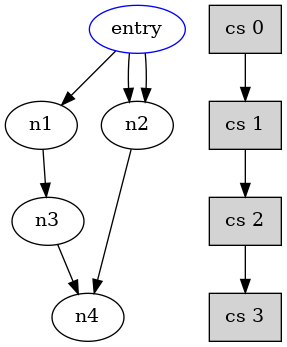
Into data flow graph, each edge represents a data value. If the value crosses a cycle step boundaries, it has to be stored into a register.
For example, in the data flow graph below, the edges from n1 to n3, from n2 to n4 and from n3 to n4, cross the low boundary of control step 1 and control step 2. Each of this edge represents a storage value and so, it has to be assigned to a register.
This can be considered the first and simpler approach to register allocation problem. This section has the goal to exploit some properties of the problem and try to reduce the number of storage modules. It is organized as follow. The subsection Principles of register allocation explains and defines the problem in other to get a more reasonable approach. Subsection Traditional approach to register allocation problem overviews the classical approach to register allocation and PandA's approach to register allocation defines the approach adopted and implemented into PandA framework. Finally, subsection Algorithms overview shortly defines algorithms implemented into registerAllocation class.
The register allocation problem is defined as finding a solution to the register allocation function  , that identifies the storage module (like registers and register files) holding a value from the set
  of values that have to be stored. A storage module has to be assigned to each storage value. If the register allocation problem is considered in isolation, the goal is to minimize the number of storage modules. Every storage value is labeled with the variable it belongs to using a function
  where
where  is the set of variables from the language.
The function  determines for each storage value the cycle step in which it is written.
The function  determines the set of cycle steps in which the storage value is read. The function
  , determines the last cycle step in which the storage value
  is read. Thus,
  .
.
A storage value v that is written in state  and read for the last time in the state
  is called life in the interval
 ![$ lt(v) = [\omega(v), P(v)] $](../../form_173.png) . The interval will be called lifetime (interval) of a storage value v. The requirement to keep storage values from one variable together is modeled by a set of lifetimes assigned to each variable
. The interval will be called lifetime (interval) of a storage value v. The requirement to keep storage values from one variable together is modeled by a set of lifetimes assigned to each variable  . The function
  describes this set of lifetimes:
Usually, from an examination of the control/data flow graph, it can be derived a conflict graph  (also called interference graph), where nodes are the storage value to be stored, and edges W are pairs of values that cannot be assigned to the same storage module because they are alive at the same time. This means that the storage values that are adjacent in cannot be stored in the same register because their interval life overlap. Concluding, two vertices are joined by an edge if they are in conflict. The complement of a conflict graph will be called compatibility graph.
Edges  of the compatibility graph
  (e.g., the complement of the conflict graph described above) are defined as follow:

and is the set of the storage values;  and
and  are the write and last read cycle steps and the operator
  returns true if two intervals overlap and return false otherwise:


This means that storage values that are adjacent in  can be stored in the same register without overwriting each others values.
A clique covering algorithm, applied to compatibility graph, groups the values in such a way that all values that belong to the same clique can be stored in the same register.
A heuristic algorithm for clique covering of compatibility graph is the Tseng's algorithm. The clique covering is done using a heuristic that first combines those nodes having the most neighbors in common. To break a tie also the number of excluded edges from the combination is calculated. One edge is selected from this set  . A new vertex
  represents the union of the cliques of
  and
and  . All excluded edges are removed from the graph and is connected to the remaining edges of . Finally, and are removed from the graph.
Solving the general clique problem will attempt to minimize the number of registers needed to store all the variables. Method registerAlg::clique_cover() implements the Tseng's clique cover algorithm.
However, there are special cases in which more efficient algorithms may be used, as explained into Algorithms overview.
It's known that finding a clique covering in a graph  is the dual problem of finding a coloring in the complement graph
  ,so method registerAlg::coloring() provides a way to solve register allocation problem by conflict graph coloring as these graph are one the complement of each other by definition and they are both provided from compatibilityGraph objects.
What said in the previous section could be considered as a conservative approach. In fact, with a further and careful analysis, the conflict graph can be pruned by unuseful constraints (e.g. unuseful interference edges) due to false conflicts among variables. So, storage values that were considered conflicting before, now can become compatible and so the number of storage modules can be further reduced. \ In particular, the analysis focuses on the fact that more than one mutual exclusive control flow can exist in the behavioural description: this means that a pair  of storage values can holds the same register (in spite of their interval life overlap or not) if
  belong to paths that are in mutual exclusion each other. \ So, in order to perform this analysis, it can be useful to use a different flow graph representation, the Reduced System Dependence Graph with information about Feedback edges (the RFSDG Graph), that contains all the information you may need afterwards about data and control dependences. This graph represents the transitive reduction of the usual System Dependence Graph (the SDG graph); it's used at this step because it shows a complete and minimum representation of all control/data flows.
Dataflow analysis, based on Appel\'s approach, has been quite modified to obtain better result in a multi-flow problem, such as a usual DFG is.
First step is usual dataflow analysis, where live variables are computed for each vertex, to get information about liveness. Liveness information (live-in and live-out) can be calculated from use and def as the following dataflow equations shows:
![$ in[n] = use[n] \bigcup (out[n] - def[n]) $](../../form_195.png)
![$ out[n] = \bigcup_{s \in succ[n]} in[s] $](../../form_196.png)
These dataflow equations for liveness analysis mean that:
 at node
  , than it is
  at all nodes in
 ![$ pred[n] $](../../form_200.png) . at node , an not in
. at node , an not in ![$ def[n] $](../../form_201.png) , than the variable is also at . That is, if someone needs the value of
, than the variable is also at . That is, if someone needs the value of  at the end of statement , and does not provide that value, then \'s value is needed even on entry to n.
![$ in[n] $](../../form_202.png) and
and ![$ out[n] $](../../form_203.png) are initialized to the empty set {}, then the equations are repeatedly treated as assignment until a fixed point is reached.
are initialized to the empty set {}, then the equations are repeatedly treated as assignment until a fixed point is reached. and not
  at the operation vertex or when there is a new definition of the same variable in the vertex. Merging nodes having to be take carefully: they also merge variable definitions.
 After dataflow analysis, conflic graph can be created. In graph creation, each edge into the control flow graph is taken into account. If source vertex and target one are scheduled into different control step, it means that a register is needed for each variable living out from the source vertex to keep value alive until target one will use them. So a conflict edge can be set between each pair of variable in a such situation: they cannot use the same register module. However, it is a conservative approach. Now, some improvements implemented into the proposed solution have been explained.
This algorithm is able to detect  variables. In fact, theorically, each vertex can execute only one operation and so store only one result. Multi-definitions are allowed only by using statements like as:

In this way, variable a and variable b are different ones but they contain the same value, so they can share the same register. In proposed solution, they can be detected because definitions have been forwarded. So, during the analysis of an edge, if two variables are both alive and definition vertex is the same, they can be considered alias and then there is not conflict between them.
There is no conflict also when the defining vertices are in mutual exclusion. In fact, at run-time, if a variable is defined by a vertex, the other one will not be defined, so register could be shared between them.
Constants and read input variables doesn't need any register. pair of variables living togheter and without any of above properties are in conflict. So an edge between them must be added into the conflict graph.
As shown in Figure \ ref{fig:flowchart}, there are four main register allocation algorithms. The best one is chosen on the basis of a precise analysis of the topology of the resulting conflict graph. In fact there are special cases in which efficient algorithms may be used.
Before describing precisely each algorithm, some definition can be useful:
The lifetimes of all values are represented by intervals. The register allocation problem can be viewed as the problem of assigning the intervals to registers along a horizontal line, such that no two intervals in the same register overlap. These intervals can be seen as wires which have to be assigned to tracks (the registers), which will make this problem analogous to the channel routing problem without vertical constraints. A left edge algorithm can be used to solve this problem.
Left edge algorithm 

Since the list of registers is pre-sorted the check if a new value overlaps with the values in the registers can simply be done by comparing the write time of the value with the last cycle step in which the register is occupied. This cycle step is called the last read step of a register: P(r).
Sorting is the most complex step in this algorithm and the left-edge algorithm can be performed with complexity  where n is the number of values to be stored. Method registerAlg::left_edge() implements previously described algorithm.
The left edge algorithm will only guarantee optimality if the life times of all variables can be ordered in a linear fashion. If the data flow graph contains conditionals this may not be the case. When variables are alive across the beginning or ends of conditionals these situations can arise. The lifetimes cannot be represented along a single line but form a tree-like structure. The confict register allocation graph is not an interval graph anymore. It can be proved that a graph G is an interval graph, if and only if it does not contain a subgraph which is a so called asteroidal triple. See [1] pag. 16-17.
Despite the fact that the asteroidal triples cause the conflict graph to be non-interval graph, they are still triangular (chordal) graphs. Algorithms exist to efficiently color these graphs. Similar to a left-edge algorithm an ordering in which to color the vertices has to be build first. A lexicographic breath first search provides such an ordering. The algorithm returns a sequence of vertices  which can be used in coloring the graph. Vertices will be picked in order of their maximal labels. Each time a vertex is picked the labels of all its neighbor vertices are updated. The sequence are compared lexicographically. The node sequence returned in
  will be a so-called perfect vertex elimination scheme.

Once such an ordering is obtained a simple modification to the left edge algorithm can be made. All values have to added to the registers in the order prescribed by . The test if a value can be added to a register becomes more complicated than a simple left edge algorithm as one cannot simply test for overlap between the read cycle step of the last value with the new value to be assigned. All values previously assigned to the register have to be checked for overlap. The following algorithm produces the minimal number of registers in case of conflict register allocation graph is a triangular graph. The complexity is O(V+W).

Method registerAlg::chordalColoring() implements the previus chordal graph coloring preceded by the lexicographic breath first search to get the node order.
Cyclic Register Allocation Algorithm is the best algorithm to apply when the conflict graph is a cyclic graph, but only when there is almost one cycle of length strictly greater than three. This is due to the fact that if the conflict graph is a cyclic graph but every cycle of length strictly greater than three possesses a chord, this means that the graph is a chordal graph and so one of the two previous algorithm are applied.
[1] L. Stok, "Data path synthesis", Integration, VLSI journal, Vol.18, pp.1-71, June 1994.
[2] Y.L. Lin, "Recent Developments in High-Level Synthesis", ACM Trans. Design Automation of Electronics Systems, vol. 2, pp. 2-21, January 1997.
[3] A. W. Appel, "Modern Compiler Implementation in Java", Cambridge University Press, pp. 1-548, 1998.
[4] R. Shamir, "Advanced Topics in Graph Algorithms", Notes of Course "\e Advanced \e Topics \e in \e Graphs \e Algorithms", Tel Aviv University, Spring 1994.
 1.8.13